
Home
>
Products > Isolate Disconnector Switch > Disconnector Switch > Pole-mounted Disconnector Switch 33KV

 Optical Fiber Cable")


Pole-mounted Disconnector Switch 33KV
Model:HRH-B/33F-630-25kA
Pole-mounted Disconnector Switch 33KV is an electrical device for the reliable disconnection of certain sections of a high-voltage electrical network when there is no current in them. The use of isolating switches (either alone or in combination with high-speed short-circuiting devices) makes it possible to simplify the arrangement of switching points and transformer substations and to eliminate expensive high-voltage circuit breakers.
In the case of damage to certain sections of a network, the circuit breakers operate first, and then the isolating switches automatically disconnect the damaged section, after which the circuit breakers close again and restore electric power to the rest of the consumers on the network. Isolating switches are also used to disconnect and reconnect unloaded transformers and sections of power lines during operation. An isolate switch must provide a reliable connection in case of a random occurrence of a short circuit in the network. An important characteristic of an isolating switch is a short operate time, particularly the disconnect time, which must not exceed 0.1 sec.
Model:HRH-B/33F-630-25kA
Send Inquiry PDF DownLoad
Product Description
Outdoor AC Gang pole-mounted disconnector switch 33KV used in 3 phase AC 50/60Hz power circuit, it is used as switching on and switch off at the voltage without load. It applies to IEC 60964: 1996, IEC62271-102:2002.
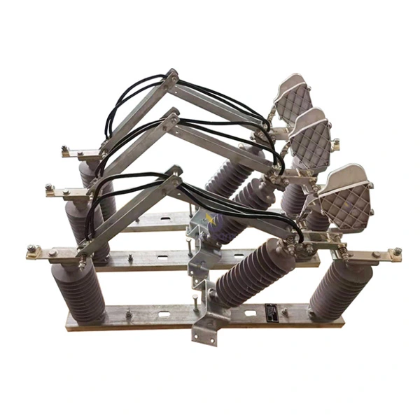
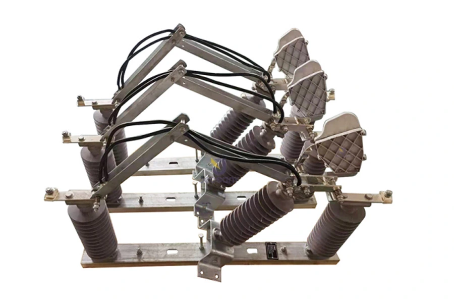
The disconnector switch is used for three-phase circuit systems, and its structure is simple, economical, and convenient. The rated current of the disconnector switch is 630, 800, and 1250 amperes. They are all composed of a base, pillar insulators, conductive parts, and operating mechanism parts to cut and close the circuit. The appearance of the disconnector switch is shown in the figure A.
2.Main features
2.1. During electrical equipment maintenance, provide an electrical compartment with a clearly visible disconnection point to ensure the personal safety of maintenance personnel.
2.2. The disconnector switch cannot be operated with load: it cannot be operated with rated load or high load, and cannot open or close load current or short-circuit current. However, if there is an arc extinguishing chamber, it can be operated with small load and no-load lines.
2.3. During general power transmission operation: first close the disconnector switch, and then close the circuit breaker or load switch; During power outage operation: first disconnect the circuit breaker or load switch, and then disconnect the disconnector switch.
2.4. When selecting diconnector switch, just like other electrical equipment, the rated voltage, rated current, dynamic stable current, thermal stable current, etc. must meet the needs of the usage situation. The function of an disconnector switch is to disconnect the no-load current from the circuit, ensuring a clear disconnection point between the equipment being repaired and the power supply to ensure the safety of maintenance personnel. Without a dedicated arc extinguishing device, the disconnector switch cannot cut off the load current and short-circuit current. Therefore, it must be operated only when the circuit breaker disconnects the circuit.
3.Environmental conditions for use
3.1. Altitude above 3000 meters;
3.2. Environmental temperature: The highest ambient temperature shall not be higher than +40℃, and the lowest ambient temperature shall not be lower than -30℃;
3.3. Outdoor wind speed not exceeding 35 meters/second;
3.4. Earthquake magnitude not exceeding 8;
3.5. The installation site should be free from gases, vapors, chemical deposits, salt mist, dust, dirt, and other explosive and corrosive media that seriously affect the insulation and conductivity of the switch;
3.6. The installation site should be free from frequent and severe vibrations.
4.Main technical parameters (Table 1)
| Type | Unit | HRH-B/33F | |
| Rated Voltage | KV | 33 | |
| Rated Current | A | 630 | 1250 |
| Short Circuit Withstand Current/Duration | KA | 25 | 25 |
| Shock Steady Current | KA | 31.5 | 31.5 |
| Impulse Withstand Voltage | To Earth | 200 | 200 |
| Across the isolating distance | 230 | 230 | |
| Power Frequency Withstand Voltage | To Earth | 70 | 70 |
| Across the isolating distance | 95 | 95 | |
5.Contact force of isolation switch (Table 2)
| Rated Current (A) | Contact Force (kgf) |
| 400 | 32-36 |
| 600 | 34-48 |
| 630 | 34-38 |
| 800 | 34-38 |
| 1000 | 50-60 |
| 1250 | 50-60 |
6.Pre installation work
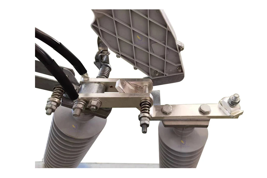
6.1. Remove dust and dirt from the components, carefully wipe the surface of the insulators, and scrub the wiring surface of the grounding screw.6.2. Apply a layer of Industrial Vaseline to the rotating parts and contact areas.
6.3. Check the contact surface and adjust the height of the compression spring to ensure that the contact pressure meets Table 2.
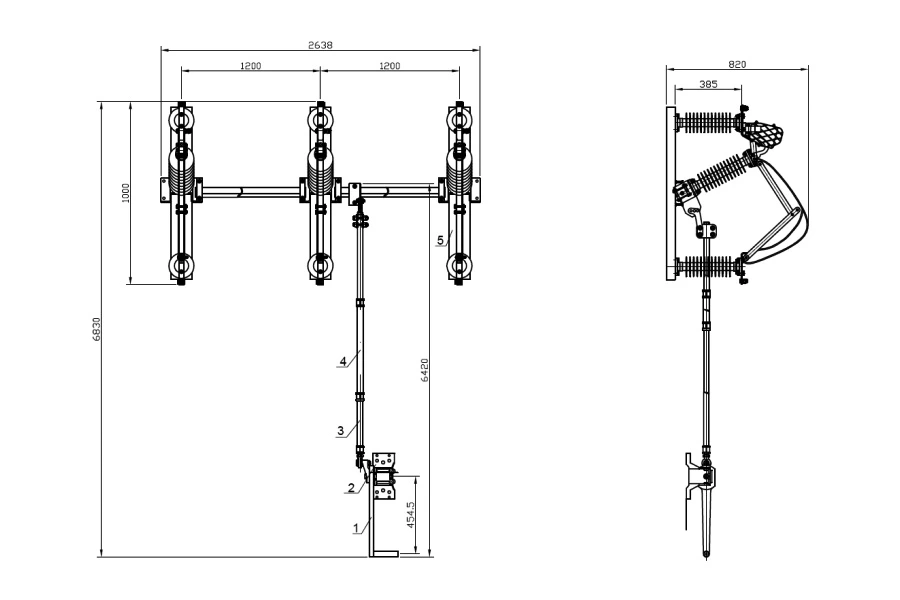
Figure A
Hot Tags: Pole-mounted Disconnector Switch 33KV, China, Manufacturers, Suppliers, Factory, Cheap, Low Price, IEC, Newest, Quality, Latest Selling
Related Category
Send Inquiry
Please feel free to give your inquiry in the form below. We will reply you in 24 hours.